Today, We want to discuss how these original control arms were designed and manufactured, the problems that it’s caused, and the decisions behind why we resolved it the way that we did.
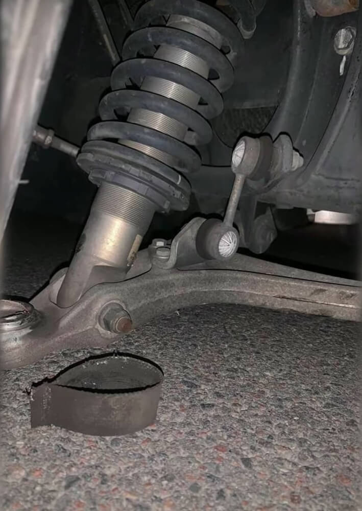
Ball Joint Failure
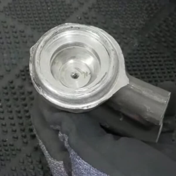
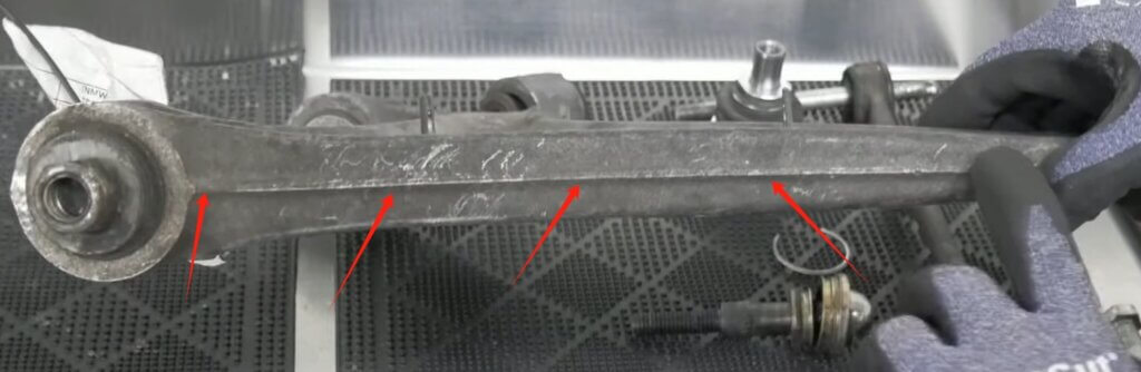
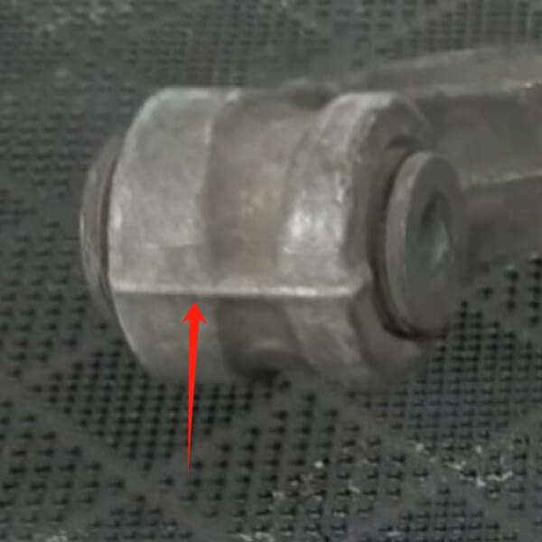
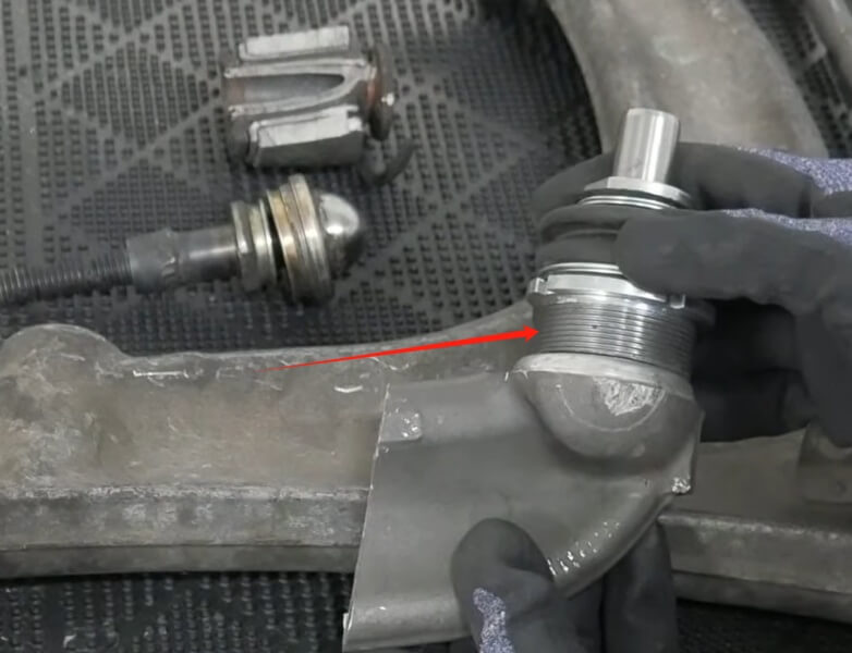
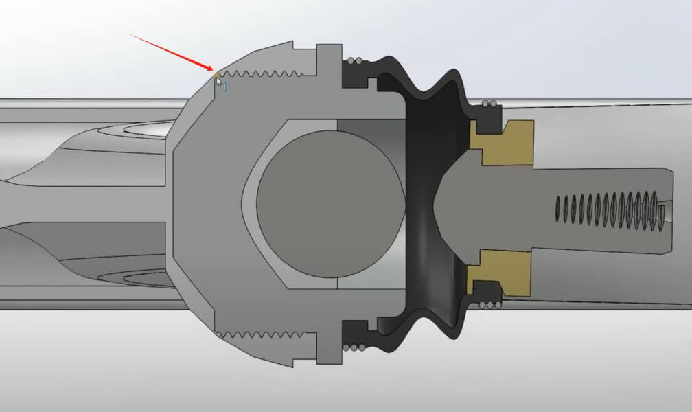
Having a look at this ball joint, it doesn’t look particularly unusual, but when you have a look at a cutaway of the control arm, you’ll see that we have this other rather unusual cutout.
A cup which would sit in the control arms.
And the reason it would sit like that is because the ball joint uses the arm itself as the seat.
Then press ball joint into the control arm, and a little piece of metal was peened across the top of it so that it would maintain its position.
This introduces a few problems.
The most obvious is that if this ball joint fails, the control arm is scrap, Since it is integral to the control arm.
Most people will tell you that you need to get rubbers inspected since they’re the cause of failure, but they have nothing to do with it, Sure, if these fail, the control arms will fail sooner.
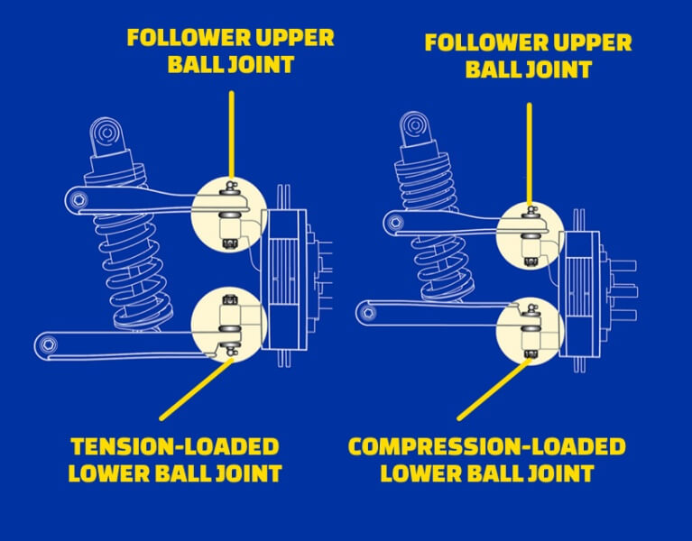
These control arms will fail regardless, and they will always fail premature to a conventional ball joint because of the way that they’re arranged, Conventional ball joints are typically arranged in compression or tension, but these control arms are arranged in compression and tension.
Every time the car accelerates or presses the brakes, this ball joint will load up in both directions. The problem is that you can only design the ball joint to be rigid in one direction, As you can see above picture that it is press fit, What that means is that once this joint is in tension, it has the chance to pull this ball joint even a fraction of a millimeter out. Once that’s done, there will be play that can never be rectified.
Press fitting into aluminium is a difficult thing to do from a design and engineering point of view, that is, technically, it’s easy to just press something in, But the problem is that the rules for press fitting are actually really, really complicated.
You have to destructively test it if you’re ever doing a unique application, to know that it’s even safe. So combine that with the fact that aluminium has some rather unique wear properties which prevent it from maintaining its rigidity over its entire life. What’s most likely happening is that just over several cycles, these are pulling forward a fraction of a millimeter, introducing play that can never be fixed.
So that’s why these ball joints are a big deal.
Materials And Manufacturing
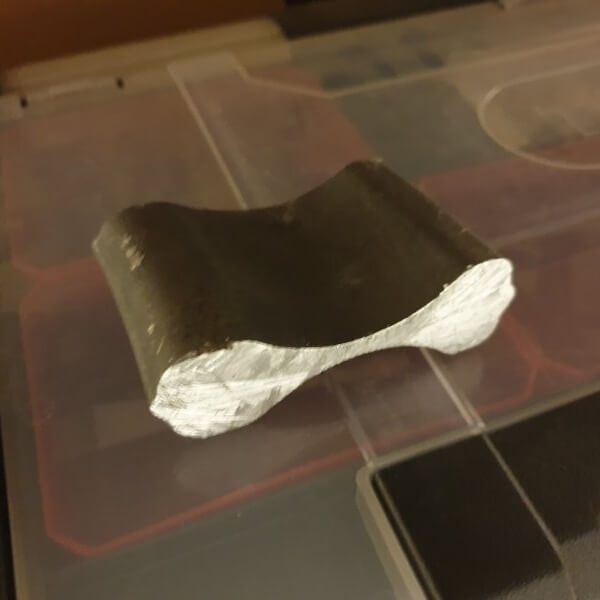
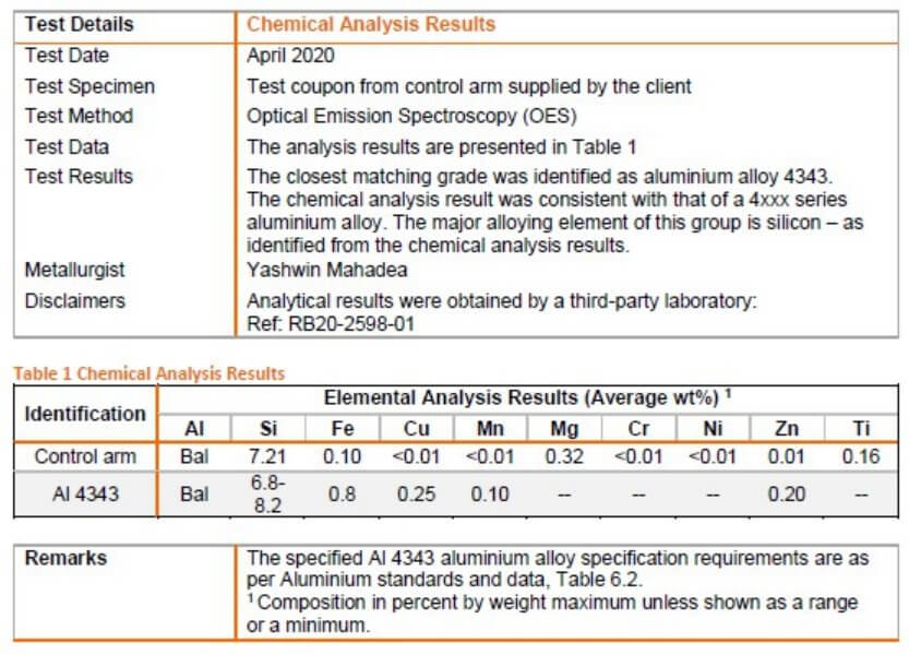
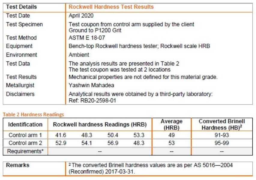
We sent a sample of this material out to a lab, and it is a grade of aluminium cored 4000 series. Chemical Analysis and Rockwell Hardness Test.
One of the interesting things about that material result is that a lot of people assumed that these were forged.
There’s no evidence at all of any surface hardening features, which indicates that these are, in fact, a casting.
Judging by the quality, they’re probably a die cast, but it doesn’t really matter, What that means is that there is a casting seam along the body, and this becomes a focal point for stresses.
Since there is no tension in the surface to try and maintain this seam, that becomes relevant when we get to the bushings.
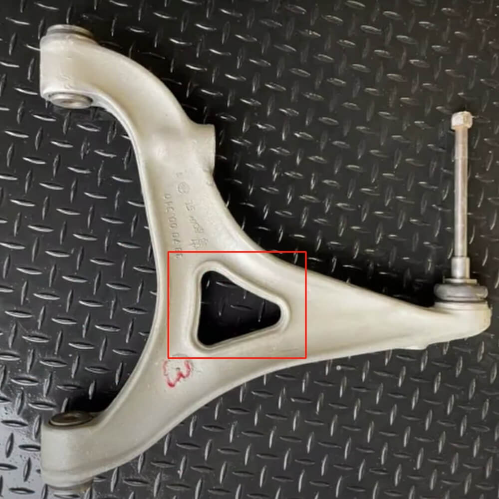
Another thing to keep in mind is there are two versions of this control arm. This is the later model, which is heavily reinforced, There’s no cutout here in the center section, which you can see in the older arm to reduce weight.
And more importantly, there is no reinforcement around these bushings on the older version. A good thing to know is that manufacturers, oems in particular, will not change a design unless they have to, because it’s a very expensive exercise.So that tells you that Maserati knew that there was a defective by design issue with these control arms.
Below pictures are the older version.
Bushing Failure
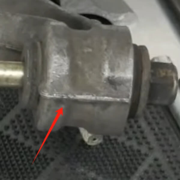
As You can see the casting seam.
Now, though, the casting seam is obvious on the outside, that casting seam is continuous through the entire body. It will be on the inside where it’s machined.
It may not be visible, but there will be a seam in the crystalline structure of the metal, When you press the bushings in, they are press fit and they provide tension outwards.
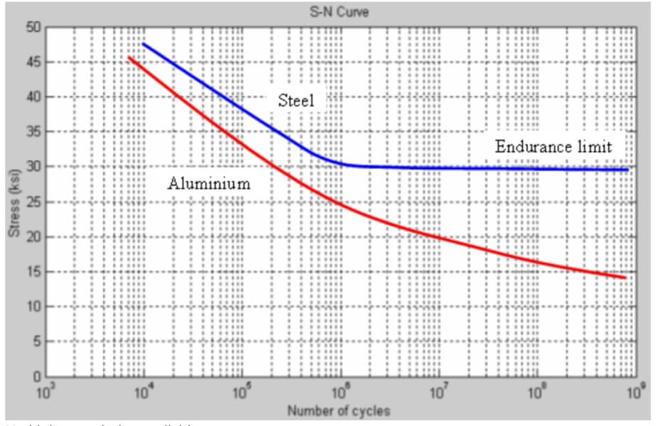
Combine that with many cycles and bumps, and the fact that aluminium has the properties, unusual properties, with its endurance limit.
What this means is that you end up with a situation where a fatigue crack can propagate through the material through to the thinnest point, which is effectively here.
Even on these reinforced arms, they do have a tendency to form cracks, Here on the older arms, they’re known to just spontaneously fail from cracking.
Please watch below video and you will see more details from FEA Analysis.
Busing Analyse
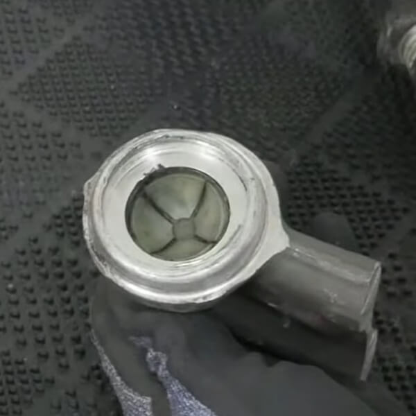
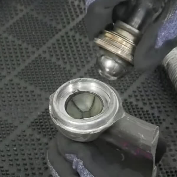
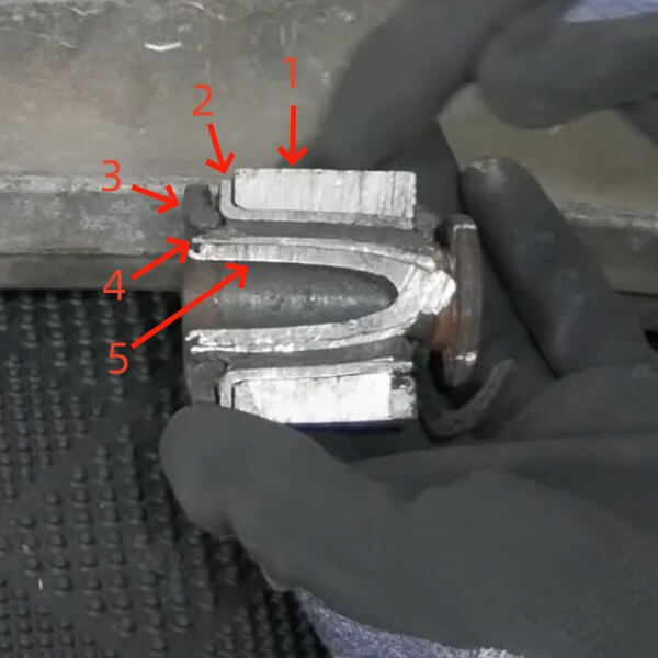
We cut Maserati bushing in half in place, So you can see a clear cross-section of it, As the right picture showing.
1. Control Arm Body 2. Metal sleeve 3. Rubber layer 4. Inner metal sleeve 5. Inner metal sleeve
So it’s effectively a bearing with a rubber isolator, two inner sleeves rotate freely against each other, and the rubber isolator helps with a bit of nvh(Noise Vibration and Harshness).
The reason that this is done is it gives you a good middle ground between a bearing in your control arms, which have very harsh nvh and they don’t have a very long life expectancy because of the direct contact that they have compared to rubber, which can absorb some degree of vibration.
But you can see quite clear there’s not a lot of rubber in the picture, So you would be getting quite a lot of vibration and force into these control arms.
Why you can't rebuild the OEM arm safely
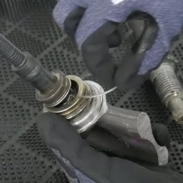
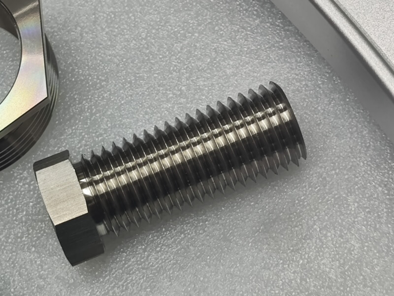
We originally considered rebuilding control arms, The first problem that we had with rebuilding these starts at the ball joint. Below are the ball joints that we used, and one of them is threaded body.
Firstly, you can’t use a steel threaded body into an aluminium threaded body.
The material properties to do with the endurance limit effectively mean that you can really only tighten it two or three times and then it will start pulling out pieces of metal.
If you’ve ever worked on an aluminium block, on an engine and you pull out some studs, a little piece of metal will always come with them.
That’s why it’s a material property of aluminium.
It’s completely irrelevant what grade of aluminium it is.
So if we wanted to rebuild control arms and cut a thread into it, We might be able to do this a couple of times, then the control arms will be completely trash anyway.
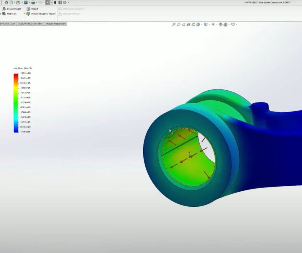
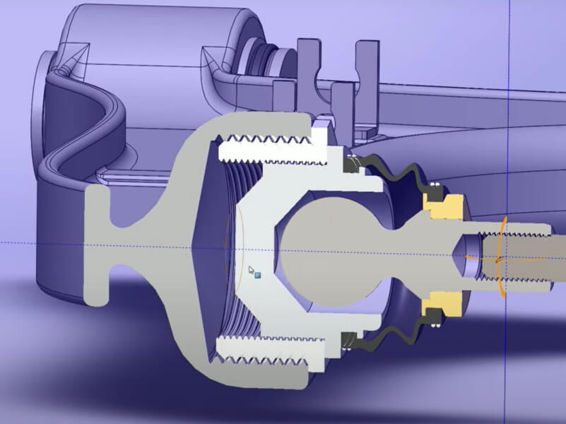
Then if you have a look at the depth that this goes into, if we removed the threads and tried to press fit it, we would be left with very little material on this.
And the FEA confirmed that there would be substantial amounts of stress in this area(Picture showing on the left)
We’d be quite concerned about fractures around a press fit, More than that, press fitting is a very imprecise science.
You can’t calculate it out from first principles, reliably, Anything that you press fit, you are supposed to do destructive testing in batches to make sure that it’s behaving the way that you expect.
Below is screenshot from the SKF installation and sort of selection manual up , just to give you an idea of how complex it is. And that’s when they’ve already done the research and they’re providing you guidance on steels.
If you are interested in this, you can read the details here.
But going steel into aluminium, they have different rates of thermal expansion, The short version is, it becomes very dangerous very quickly.
To do a press fit on something like this Without doing the correct analysis. So just on this piece alone, We wouldn’t have been able to proceed with a safe rebuild of the control arms.
Some people trying to replace the bushings, And during that process, they’ve split the control arms. There’s really no point trying, It’s just going to be a waste of time.
And if we do succeed, it’s very likely that there’s going to be hidden or invisible cracks, And then it’s going to be very high risk of fatigue cracking up in the ball joint as well.
It just wasn’t a safe way to proceed, And that’s why we decided to make our own control arms from scratch.
The Brand New Control Arms
You can watch the right side video to get the details
1. The control arms are made from billet, So they do not have a casting seam, And as you can see they’re further reinforced, Even compared to the late model control arms.
2. Since they’re made out of a single piece, It’s actually cheaper in terms of manufacturing time, To just do a single pass like that, Instead of to use less material.
Since we are removing material to manufacture the control arms, Whereas the OEM arms are adding material. They were trying to save money by making a smaller casting, In this case, it allows us to make these more reinforced effectively, With no cost penalty.
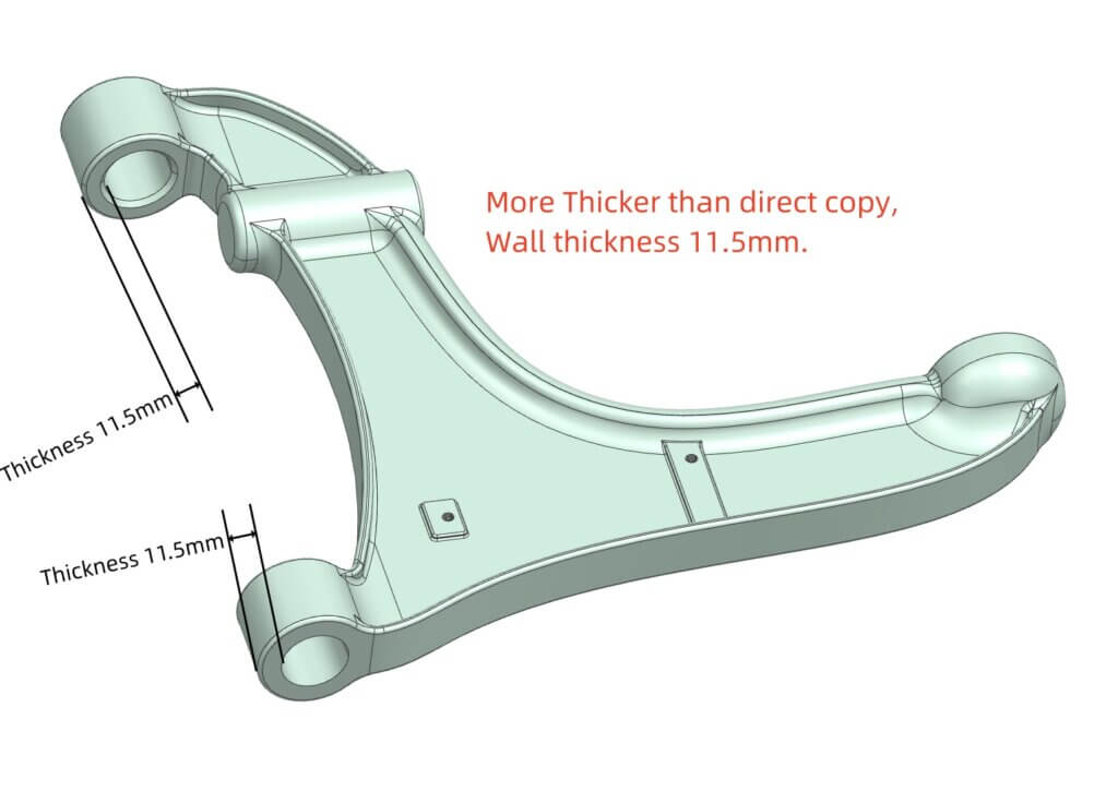
Compared to making them a direct copy, We can design the wall thickness more thicker(see right picture), And no point for fatigue to form using the correct bushings, These will be serviceable for a much longer period of time.
Another difference with these control arms is the concerns of the mechanic, The bushings can be inserted from one side, And can be easily pulled through using a bolt, which is shown in the assembly video.
This allows these bushings to be pushed out easily at a later date, When this arm is intended to be rebuilt.
Not something that is easy to do with the OEM arms, You need special tooling to reach, To be able to push the bushing from the inside, Whereas you can just sit this on a press and push it from both sides without any trouble.
The Material Of Brand New Control Arms
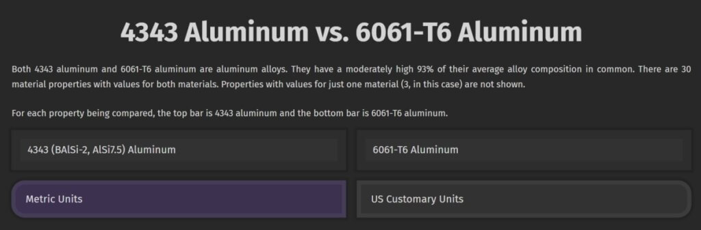
The control arms was made by 6061-T6 Aluminum, This is a much stronger material.
below are some data showing you a comparison between the 4000 series that the OEM control arm is and the 6000 series that the brand new control arms was manufactured from.
If you are interested in this, you can read the details here.
What this means is that we could technically make these substantially lighter than the OEM control arms and still exceed their strength, However, We’ve chosen not to do that.
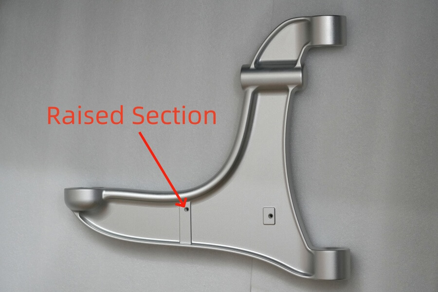
At the completion of the FEA, We have instead decided to focus on making these substantially stronger than the OEM control arms, which is also why the little raised section is here.
The FEA showed this as a point where stress was building up, so We decided to introduce that as another reinforcement.
These control arms have a calculated factor of safety of 20.
What that effectively means is that the expected stresses that these are to see these can see approximately 20 times that stress level.
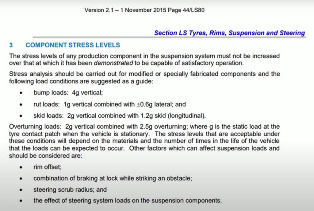
Australian Design Rules and FEA
The final step in making sure that these control arms were safe to implement was to contact an automotive engineer in Australia and get their advice on making sure that these control arms met the australian design rules.
Now, the australian design rules are for modified vehicles and these arms are OEM replacements.
So they don’t technically need to meet those guidelines as they’re substantially more stringent and onerous than what would have been put on the OEM.
However, We thought it would be good to compare them to the ADR’s, see below.
The final DATA were sent off to an engineer using a analog model of the upper and lower control arm.
The following video is about FEA(finite element analysis) analysis results.
In this real world analysis, since they’re Aluminium, they will eventually fail.
But that should be well outside of the lifetime of the vehicle, or at least my lifetime, so that We’ll be long dead before it becomes a problem.
Making the ball joint replaceable
As We said previously, We cannot reasonably re-use the OEM control arms if We thread a steel bodied ball into an aluminium receptacle. So, as discussed in the assembly video, We use a steel sleeve which is permanently affixed into the arm, which allows us to repeatedly remove and install ball joints.
Anticipating the replacement of these ball joints due to the nature of failure, this seemed like the best option to maintain the serviceability of these arms into the future.
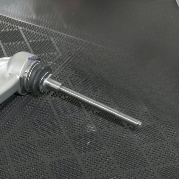
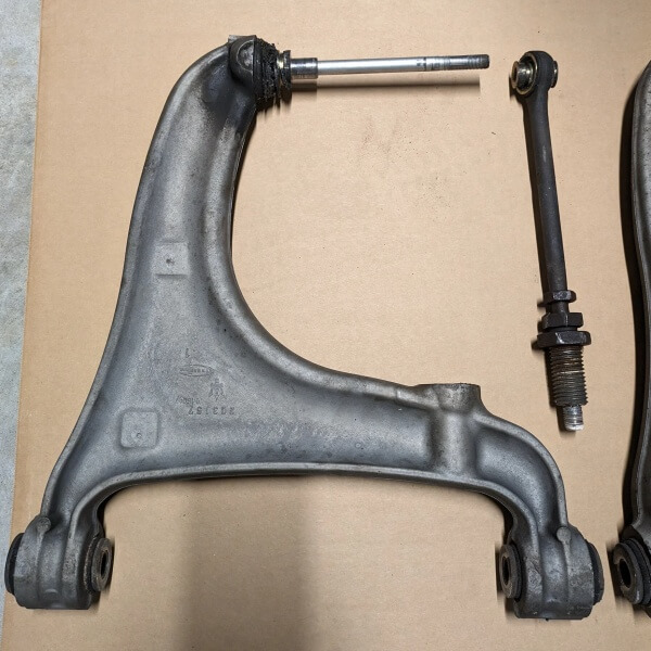
And as shown in the install video, these studs have been manufactured as part of the arm to make them more serviceable than the OEM component, simply because they have a stud on them, have a hex on them for a socket, so that they can be easily removed when the arm needs to be removed, showing as below left picture.
For comparison, right picture is one of the OEM toe adjusters, We wasn’t able to remove the stud.
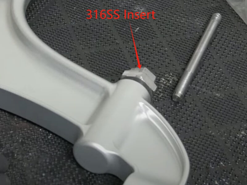
The insert for the toe adjustment below is made out of 316 stainless steel, This is to assist with corrosion, preventing this from being adjustable in the future, Combined with anti seize, these should have a much longer life expectancy than the original parts.
FEA comparison between OEM and brand new control arms